You may have the right idea regarding the attack angles, so here is a couple more measurements that I hadn't pursued.....
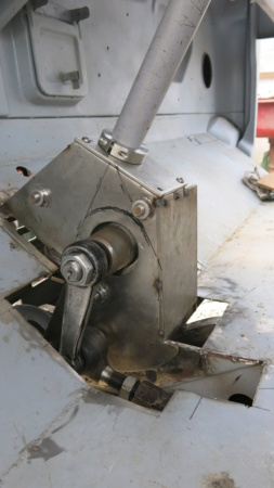
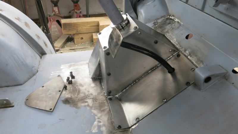
The drag-link hole in the pittman arm at direct vertical is three inches above the spring hanger bolt and three inches AHEAD (your diagram shows it behind).....
Now, I need to stop right here and state that straight vertical pittman arm placement is the halfway point, lock2lock, but isn't necessarily the factory clocking.....I was using vertical clocking to describe relative steering box location because it's easy to describe and is how mine is set up....
Again..... Bump steer is only really an issue closest to the center of about 60 degrees of steering wheel travel while you are trying to go straight at speed.....
I'm intrigued by the idea that the arcs of the two drag link arms would be set to cross over 90 degrees at different points in their travels to diminish the bump.....
I still can't think of a way to mathematically prove the concept short of making physical models using the measurement parameters that will work with what you are doing...
Maybe make a fixture that can hold the pittman arm end of the drag link in fixed locations at different heights and distances and, using an adjustable drag link, try the different positions out by bolting the drag-link into different positions on the fixture and bouncing the truck to see if bouncing turns the wheels...This would establish where the drag-link hole in the pittman arm needs to be...What I'm visualizing as this "fixture" is a steel plate fastened vertically and longitudinally in basic alignment with the pittman arm hole that can be drilled with various experimental drag link actuation locations to find the placement that most reduces growth and shrinkage in drag-link length (bump steer) as the suspension moves vertically....


