VintAGE-Vans

Would you like to react to this message? Create an account in a few clicks or log in to continue.

BRINGING IT ALL TOGETHER.... A's, G's & E's


+2
Chroma66
wideload
6 posters

    First Gen Wiring Diagram

    wideload
    wideload
    Moderator 1st Class
    Moderator 1st Class


    Number of posts : 1389
    Location : Kevil, Kentucky
    Age : 71
    Registration date : 2008-05-11

    wiring - First Gen Wiring Diagram Empty First Gen Wiring Diagram

    Post by wideload Mon Dec 05, 2011 9:22 am

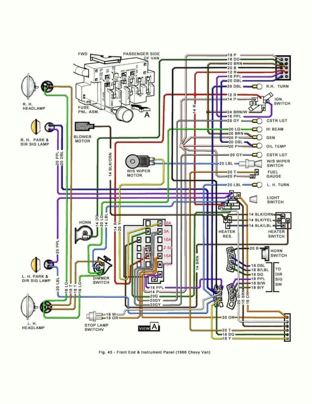
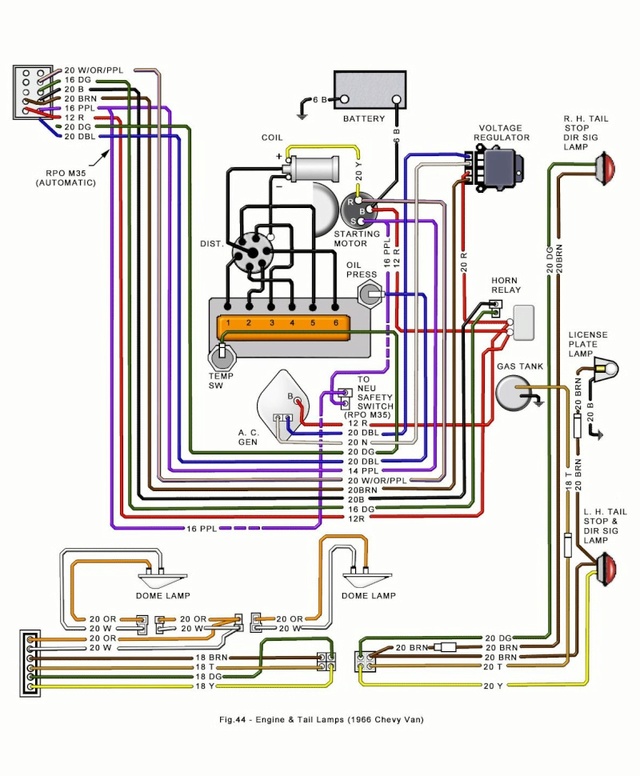
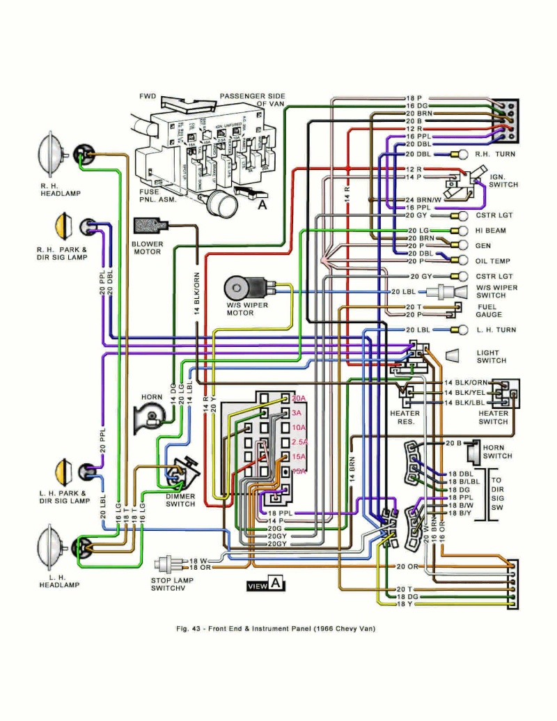
    A couple of our members took the time to produce these (Viewmaster and Danthevanman). Just thought they should be here so everyone could access them easily. They have been very helpful to me!!! Thanks Carl and Dan!!!!!!!


    wiring - First Gen Wiring Diagram 1st_ge10

    wiring - First Gen Wiring Diagram 66_wir10

    wiring - First Gen Wiring Diagram 66_wir11

    You can right click on each and save them to your computer then print and tape together for a real nice wiring diagram. Or left click on the image to view the full page.


    Chroma66
    Chroma66


    Number of posts : 101
    Location : Seattle, WA
    Registration date : 2011-03-02

    wiring - First Gen Wiring Diagram Empty Re: First Gen Wiring Diagram

    Post by Chroma66 Tue Mar 17, 2015 11:19 pm

    Having a wiring diagram is AWESOME. I Googled "1966 chevy G10 wiring van schematic" and all the images were from VintAGE Vans! None as good as these though, cannot thank you guys enough. I get my starting wire tomorrow!
    Vantasia
    Vantasia


    Number of posts : 1412
    Location : New Jersey
    Age : 70
    Registration date : 2013-08-18

    wiring - First Gen Wiring Diagram Empty Re: First Gen Wiring Diagram

    Post by Vantasia Wed Mar 18, 2015 3:59 am

    Used 'em several times!
    VANagain
    VANagain


    Number of posts : 1048
    Location : San Diego, CA
    Age : 63
    Registration date : 2008-05-16

    wiring - First Gen Wiring Diagram Empty Re: First Gen Wiring Diagram

    Post by VANagain Sun Jul 17, 2016 12:42 am

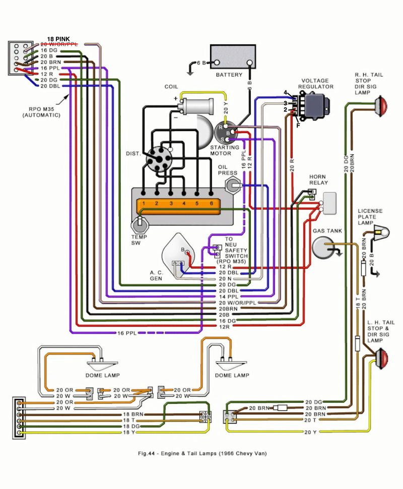
    There is a slight error on Engine & Tail Lamps diagram above. The wires are off by one vertically on the terminal shown in the upper left. That's the plug in the doghouse that connects to the Front End loom. I told the guy who made these and he sent me this fixed one:

    wiring - First Gen Wiring Diagram 1st_ge10
    lzxlz
    lzxlz


    Number of posts : 40
    Location : beaverton/ PDX
    Registration date : 2015-08-29

    wiring - First Gen Wiring Diagram Empty Re: First Gen Wiring Diagram

    Post by lzxlz Mon Apr 24, 2017 1:17 pm

    This is great for reference. I have a 1966 G10 w/ 230 and manual. The cable of wiring coming
    into the doghouse does not match this diagram for a few colors. Are there variations? The wiring on my van looks to be original but how can I tell for sure? is there a specific type of cable cloth or a certain type of wire wrapping that would identify it as original?
    Also note: There is not any splicing, patches, junctions or connections between the doghouse wiring and the cluster wiring. It perfectly joins into and matches the other larger sections of wiring and wire wrapping that go to other parts of the van. So, unless the entire vehicle was re-wired ??? as far as I can see, the doghouse wiring wrap seems to match up with everything else.
    Hopefully, I am not facing a total do-over of someone else's lazy color coding/electrical work. I have rewired everything to be as closely to the diagram as possible and everything seems to work except the GEN/FAN "idiot" light is always on when the engine is running. I have a post about that issue which may be related to the ignition switch.
    VANagain
    VANagain


    Number of posts : 1048
    Location : San Diego, CA
    Age : 63
    Registration date : 2008-05-16

    wiring - First Gen Wiring Diagram Empty Re: First Gen Wiring Diagram

    Post by VANagain Wed Apr 26, 2017 11:20 pm

    Your van has definitely had some rewiring done if you don't have the connector between the Front End wiring and the Engine wiring. All of the 1st Gens had it, along the side of the doghouse near the carburetor. It's the connector shown in the upper corner of the wiring diagram, that carries over from one page to the other. Consider yourself lucky that this connector has been eliminated. They very often fail because it gets so hot there and the terminals inside the plastic connector are pretty small. So when it fails, most people just eliminate it.

    The stock wire loom was wrapped in what looks like black tape (but isn't—it's Non Adhesive Wire Harness Wrapping Tape).

    One wire on the diagram you might not have if you have a manual transmission is the dotted purple one coming from the coil, going to the neutral safety switch on the automatic tranny. However, with a 66, you should have a similar wire for the backup lights.

    The GEN FAN light should only be lit when the key is on but the engine is not running, or if your alternator is not putting out any current. My guess is they called it GEN FAN because either the alternator (formerly a GENerator in older cars) is not charging, or the FAN belt came off. (I was interested to learn that, when the key is ON, there is power going to one side of the GEN bulb, and from the other side a brown wire goes to the voltage regulator, which is ground when the alternator is not spinning. That's why that light is always on when you turn the key to ON but don't start it. When the alternator is spinning, that same wire changes from ground to 12V. The bulb won't light with positive 12V going to both of its terminals! But, if something goes wrong, and the alternator is not charging, that wire becomes ground again. I think it's funny that we see that light lit every time we turn the car on, or if the engine dies but the key is still on, and we never think anything of it. But if it were to come on while we're driving, I bet we would realize that something's wrong.)

    And, speaking of idiot lights, I think most know that the other one, that says TEMP PRESS, is a warning light for both coolant TEMPerature and oil PRESSure. If you look on the Front End page, the diagram shows a dark blue wire coming from the Oil Temp light to that main connector, and then find that same terminal on the Engine page and you'll see it has TWO wires coming out of it: blue to the oil pressure sending unit and green to the coolant temperature sending unit. If either one of those sending units sees trouble, it grounds its wire, causing the bulb to light. I guess GM figured either way, if that light comes on, you'd better pull over. After that you can determine whether it's overheating or you're out of oil. Now that I think about it, you can find out by pulling the wire off one of them. If the light goes out, that's the one sending the warning.

    More about that main connector. Even though the connector has 10 conductors, it only uses 7 of them. I've been able to find some replacements that are better than the original. I'll do a separate post on that.
    Chris S likes this post

    lzxlz
    lzxlz


    Number of posts : 40
    Location : beaverton/ PDX
    Registration date : 2015-08-29

    wiring - First Gen Wiring Diagram Empty Re: First Gen Wiring Diagram

    Post by lzxlz Sun Apr 30, 2017 10:06 pm

    Hey, thanks for the info. I was wondering why the wires were messed with. The wiring diagram is a little misleading but I finally figured out the subtle issues. My confusion and some of my wiring question was about the color of the top wire on the engine wiring diagram. It shows as kind of a pinkish-white color but it is labeled:
    20 W/OR/PPL It should actually be labeled PINK in 18 gauge to match up with the front end wiring diagram. It was probably a mistake. That with the other "extra" green wires and the disconnected wires for temp and oil idiot lights led to a lot of confusion with the messy wiring patches I had to sort through. The previous voltage regulator was also connected in the wrong sequence and other wires connected in the incorrect sequence to the ignition. I would like to re-label this diagram and also put down the blade assignments for the voltage regulator- I had to reference the sequence off a Chevy truck voltage regulator (of the same type) and that took a bit of searching in chevy forums to find.
    It's all working perfectly now except I found a slight drain coming off the crusty fuse box That will be next up for re-wiring, especially now that I have the diagram color riddle solved.
    lzxlz
    lzxlz


    Number of posts : 40
    Location : beaverton/ PDX
    Registration date : 2015-08-29

    wiring - First Gen Wiring Diagram Empty Re: First Gen Wiring Diagram

    Post by lzxlz Thu May 11, 2017 12:33 pm

    Wiring Diagram updated with label on pink wire mistake + specific voltage regulator wire IDs.
    lzxlz
    lzxlz


    Number of posts : 40
    Location : beaverton/ PDX
    Registration date : 2015-08-29

    wiring - First Gen Wiring Diagram Empty Re: First Gen Wiring Diagram

    Post by lzxlz Thu May 11, 2017 12:34 pm

    wiring - First Gen Wiring Diagram 66_wir12
    vanny
    vanny
    Moderator


    Number of posts : 14778
    Location : Ashburnham, MA
    Age : 65
    Registration date : 2012-09-22

    wiring - First Gen Wiring Diagram Empty Re: First Gen Wiring Diagram

    Post by vanny Wed Mar 28, 2018 7:22 am

    I'm reimporting these so that they don't get cut off:

    wiring - First Gen Wiring Diagram 1st_ge10

    wiring - First Gen Wiring Diagram Fig43g10

    wiring - First Gen Wiring Diagram Fig44g10

    And the last one with the changes:

    wiring - First Gen Wiring Diagram 1st_ge11

    And this one with the Pink change that lzxlz added:

    wiring - First Gen Wiring Diagram 66_wir10


    _________________
    “The future will soon be a thing of the past."

    http://public.fotki.com/Vintage-Vans/vintage-vans-es/ruff-diamond-1/?cmd=fs_slideshow

    Sponsored content


    wiring - First Gen Wiring Diagram Empty Re: First Gen Wiring Diagram

    Post by Sponsored content


      Current date/time is Mon Nov 18, 2024 4:45 am