


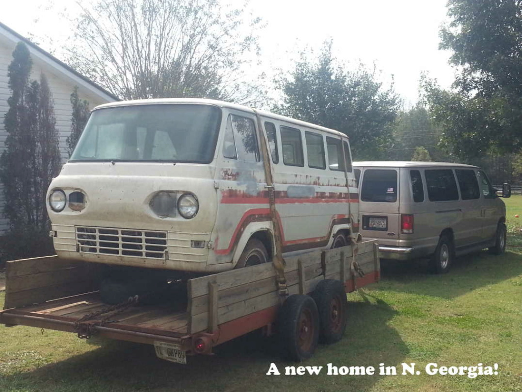
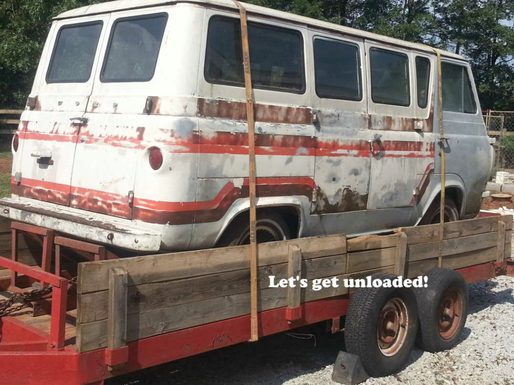
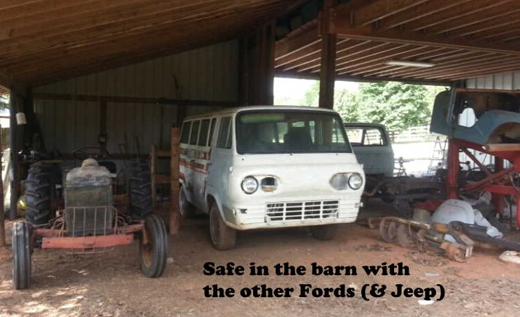
The 1965 Falcon Van was purchased over 2 years ago in Spartanburg, SC and trailered home to Danielsville, GA where it "rested" in the barn (with other Fords) until I could find the time to start on it. The previous owner was a self-employed plumber who intended to use it for business but had a dog house fire which destroyed those plans.
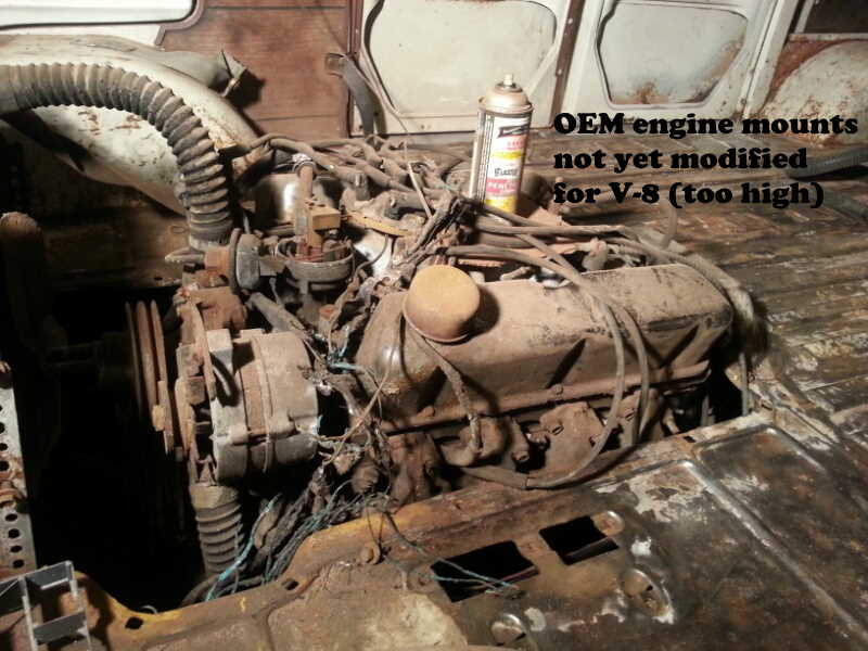
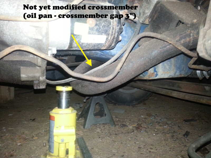
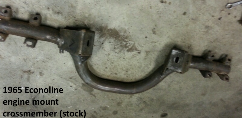
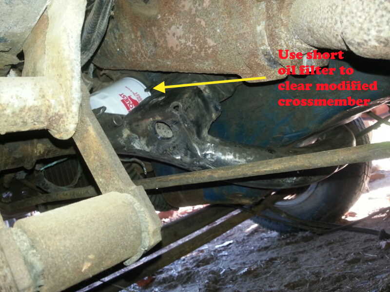
An owner before him had installed an early 80s 302 with C4 and didn't modify the stock crossmember for the V-8, which had the engine sitting high in the dog house and probably contributed to conditions which led to the fire.
I've restored two Airstream travel trailers, two boats (I/O, outboard), and a 73 CJ-5 but never a van, although we did have a 1969 Ford Club Wagon growing up in the 70s. (With 9 children of our own, we've owned (until very recently) a 15 passenger E-350 7.3 PSD for over 16 years but now that they've grown up....need to downsize.)
Having started the conversion, I'll try to share as much info as possible (and narrated pics) that will be helpful for others who may be on the fence about whether to do the conversion. That includes sharing a few mistakes along the way, as much as I'd prefer to forget them.
Big thanks and shout out to Armyof6, who's IFS thread on this forum was very informative and insightful. "Navyof11" doesn't quite have the same ring to it (6 years USN) so I'll keep "pizzachop".
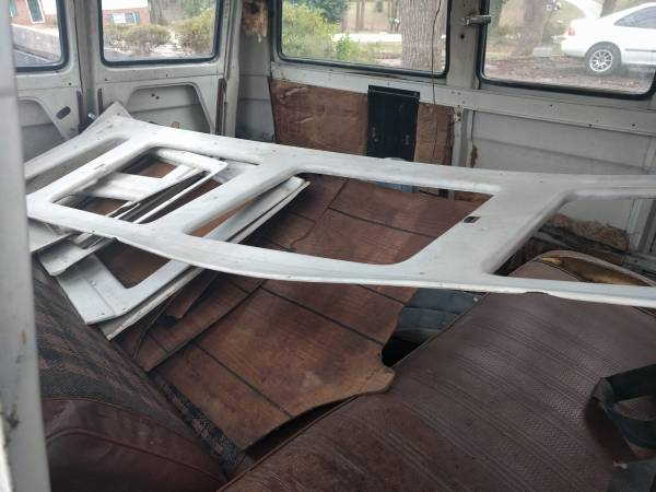
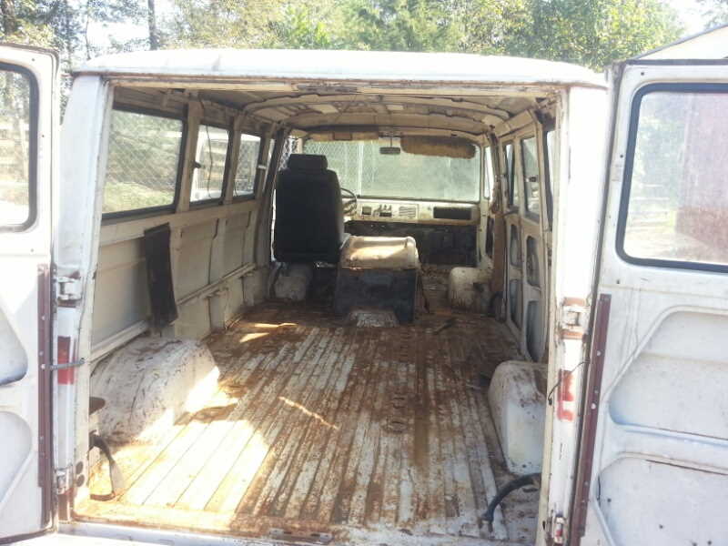
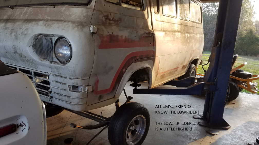
Below are pics from the day it came home.
An owner before him had installed an early 80s 302 with C4 and didn't modify the stock crossmember for the V-8, which had the engine sitting high in the dog house and probably contributed to conditions which led to the fire.
I've restored two Airstream travel trailers, two boats (I/O, outboard), and a 73 CJ-5 but never a van, although we did have a 1969 Ford Club Wagon growing up in the 70s. (With 9 children of our own, we've owned (until very recently) a 15 passenger E-350 7.3 PSD for over 16 years but now that they've grown up....need to downsize.)
Having started the conversion, I'll try to share as much info as possible (and narrated pics) that will be helpful for others who may be on the fence about whether to do the conversion. That includes sharing a few mistakes along the way, as much as I'd prefer to forget them.
Big thanks and shout out to Armyof6, who's IFS thread on this forum was very informative and insightful. "Navyof11" doesn't quite have the same ring to it (6 years USN) so I'll keep "pizzachop".
Below are pics from the day it came home.