


just picked up a 1967 Chevy P30 1 ton grumann Olson and having charging problems, the instrument panel is just like the ones in the 2nd gen G vans, I am guessing the light and ignition switches are the same too? strange/dumb question is.....does the charging system run thru either of those switches, could one of them be the culpret ? I pulled the Alt. and took to kragens and put it on tester , tested good, voltage regulator is also new, I charge the battery to 12 volts then start the van and the volt meter shows 11.88 on the battery when running ......... 
5 posters
1967 wireing diagram/ charging problems

sparky- Number of posts : 195
Location : California!
Registration date : 2010-01-05

donivan65- Governor

- Number of posts : 12248
Location : San Diego, California
Registration date : 2008-05-12
Well if you got the fan belt on,,,,,see that you got 12 volts at the big output terminal at the alternator,,,,,,put 12 volts to the right side terminal,( F) ,,,and the alternator should charge,,,,if it does, then its a wiring problem,,,,,
sparky- Number of posts : 195
Location : California!
Registration date : 2010-01-05
Hmmm...? I know I do have 12 volts at that output terminal, there is one green wire and one black wire in a plug that is plugged into that square hole with two spade connectors sticking out, seems like the green one is on the left of the plug.... so the black one must be connected to the "F"
Last edited by sparky on Sat Nov 19, 2011 9:45 pm; edited 1 time in total
donivan65- Governor
- Number of posts : 12248
Location : San Diego, California
Registration date : 2008-05-12
,,,,,,,and then we can talk about how to fix the wiring,,, (hook a ground wire to the voltage regulator base will be one of the tests)
donivan65- Governor
- Number of posts : 12248
Location : San Diego, California
Registration date : 2008-05-12
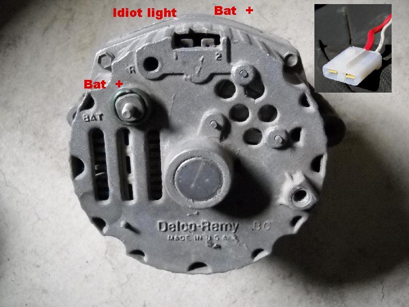
This 3rd Gen internal voltage regulator alternator will plug right in,,,,,gets rid of that old voltage regulator and all its wiring,,,,it's basically a 1 wire,,,,,,
sparky- Number of posts : 195
Location : California!
Registration date : 2010-01-05
Thanx, so what happens to all the wires going to the voltage regulator and resistor ? it all gets disconnected ?
donivan65- Governor
- Number of posts : 12248
Location : San Diego, California
Registration date : 2008-05-12
(I guess you could sell them on Ebay),,,,,actually, on the 3rd Gen Alternator, the Idiot light wire that goes to the voltage regulator gets plugged into the #1 spot and you run a jumper from #2 to the output with the battery wire on it,,,,you can check out the wiring on your voltage regulator if you want,,,,add a ground to it and if if still don't charge, you need a regulator,,,or get the $29 Autozone special and throw away all that wiring,,,,
sparky- Number of posts : 195
Location : California!
Registration date : 2010-01-05
so the output terminal (B+) needs a wire going from there to the battery or can it go to the starter ? what guage should it be ? Thanx !!donivan65 wrote:(I guess you could sell them on Ebay),,,,,actually, on the 3rd Gen Alternator, the Idiot light wire that goes to the voltage regulator gets plugged into the #1 spot and you run a jumper from #2 to the output with the battery wire on it,,,,you can check out the wiring on your voltage regulator if you want,,,,add a ground to it and if if still don't charge, you need a regulator,,,or get the $29 Autozone special and throw away all that wiring,,,,
donivan65- Governor
- Number of posts : 12248
Location : San Diego, California
Registration date : 2008-05-12
That is the wire that is on your alternator output right now,,,,HOWEVER,,,,,you really should put a fresh new 10 gauge wire going from it to the starter solenoid, and there should be a fusible link right where it connects to the positive battery cable. And #2 terminal also needs some battery so you add a ring terminal and hook it to the output terminal to that white connector that they sell,,,but check your voltage regulator connector,,,F goes to F, R goes to R, #3 is Battery, #4 is from the ign/idiot light,,,,the alternator needs these wires to be right before it will start charging,,,,
donivan65- Governor
- Number of posts : 12248
Location : San Diego, California
Registration date : 2008-05-12
Last edited by donivan65 on Sat Nov 19, 2011 11:24 pm; edited 2 times in total
sparky- Number of posts : 195
Location : California!
Registration date : 2010-01-05
ok, Thanx Don, I better read this tomorrow man, things are a little blurrrry right now! I wanna convert to the 3 wire alt. you said... "And #2 terminal also needs some battery so you add a ring terminal and hook it to the output terminal to that white connector that they sell" .............. white connector ?
sparky- Number of posts : 195
Location : California!
Registration date : 2010-01-05
Thanx man, I think I got it !! you da 
donivan65- Governor
- Number of posts : 12248
Location : San Diego, California
Registration date : 2008-05-12
We give you choices here,,,,you can fix it, replace it or upgrade it,,,,,,
sparky- Number of posts : 195
Location : California!
Registration date : 2010-01-05
I think I am gonna go with that upgraded 3rd gen 3-wire type you showed, I bet you were thinkin... WTF ! do I have to draw you a picture ? I guess you did haa, IT WORKED!! I think I got it now, gonna do the upgrade tomorrow hopefully. Thanx !!donivan65 wrote:We give you choices here,,,,you can fix it, replace it or upgrade it,,,,,,

whopman- Number of posts : 387
Location : Columbus, Ga
Registration date : 2010-04-01
Donovan what does the F and R wire stand for ?

Twinpilot001- Number of posts : 6186
Location : spokane ,Wa.
Registration date : 2009-09-28
regulator & field terminals on alt.
donivan65- Governor
- Number of posts : 12248
Location : San Diego, California
Registration date : 2008-05-12
That R is for Relay,,,it turns on the Field relay in the Regulator which sends the voltage back through the Field to energize the windings in the rotor and make electricity,,,,and I just put that R on the voltage regulator connector to make the circuit look simple, the official way is F 2 3 4. And you can see on the 3rd Gen internal regulator alternator, they call those terminals 1 and 2,,,,and they are NOT the same as R and F,,,,1 is from the idiot light and also turns the regulator on,,,,2 is the voltage sensor,,,,and I like that that one,,,,you can adjust the output voltage by moving that line,,,the way I have it, it monitors the voltage at the alternator,,,you can move that line closer to the battery if you see that the battery needs a higher charge,,,
donivan65- Governor
- Number of posts : 12248
Location : San Diego, California
Registration date : 2008-05-12
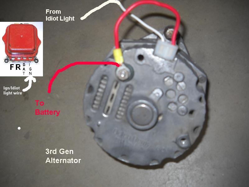
If you want to talk about repair and upgrade,,,here is a little clearer version of what we are talking about,,,,there are a lot of things to check if your alternator aint charging,,,and the 40 year old wiring is a main cause,,,,just look at the voltage regulator,,lots of wiring,,,so they decided to put the regulator INTO the alternator on 3rd Gens,,,,and here is a trick if you are lazy or don't have much time to convert to a 3rd Gen Alternator,,,,its all about getting battery to the #2 and the idiot light to #1,,,the wires are in the voltage regulator connector,,,you can just send those signals to the new alternator using those old F and R wires, by jumping across the at the voltage regulator connector,,,,you need a new connector for 1 and 2,,,some people use spade terminals,,,,


Army of Six- Number of posts : 241
Registration date : 2010-10-02
donivan65 wrote:
I thought that the white connector (connector 2) is supposed to be wired to a 12 volt ignition ON circuit. Because its purpose it to excite the rectifier when the ignition is on so it will start charging when the alternator starts spinning vs a one wire setup that wont start charging until you rev the motor up a second (which excites the rectifier). if you have it wired up directly to the battery wont the recitifer constantly be excited..running the risk of burning it up as the car is parked? thats how it was explained to me.
donivan65- Governor
- Number of posts : 12248
Location : San Diego, California
Registration date : 2008-05-12
That is a good question,,,,But if you put the ignition/idiot wire from the van to #2, that means constant voltage ends up on #1 and that is wrong,,,it will kill the battery because #1 is a drain,,,I see that a lot when people mix up those wires,,,and #1 is kind of special,,,the idiot light has a resistor in it because since the Distributor is also on the same circuit as the idiot light the regulator could feed back enough voltage to keep the Distributor energized and the engine keep running even with the key off. You need to add a resistor to #1 if you put that Alternator on ANYTHING that only has a Ammeter and no idiot light,,,,
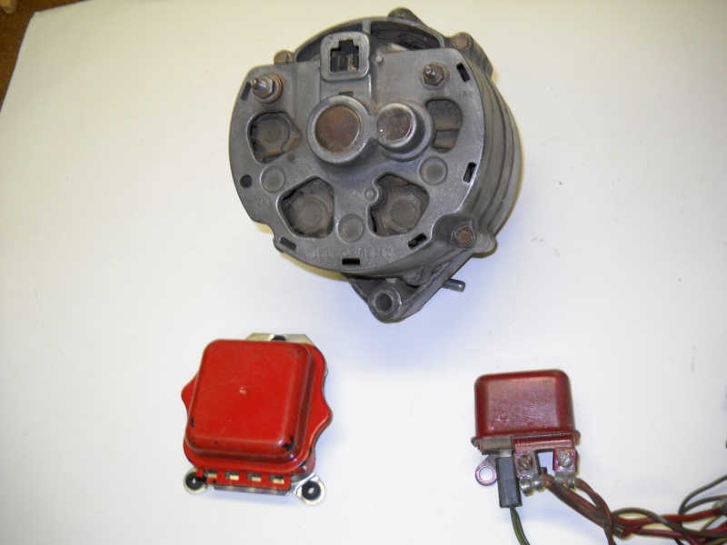
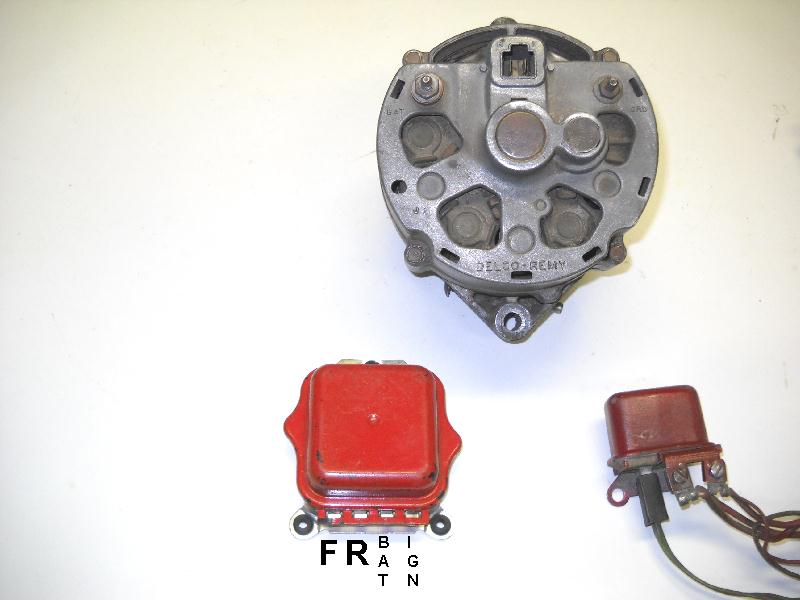
So lets look at the regulators,,,they take the solenoids and contact points and wiring and squeeze it all into this little transistorized unit and slap it into a 3rd Gen Alternator,,,

So lets look at the regulators,,,they take the solenoids and contact points and wiring and squeeze it all into this little transistorized unit and slap it into a 3rd Gen Alternator,,,
donivan65- Governor
- Number of posts : 12248
Location : San Diego, California
Registration date : 2008-05-12


