


While driving I notice the Fuel and Temp.gauges being unsteady,the pointere are slowing moving back and forth. Any thoughts ?
+2
donivan65
gary h
6 posters
Unsteady Gauges

gary h- Number of posts : 474
Location : tn.
Registration date : 2012-10-19

donivan65- Governor

- Number of posts : 12220
Location : San Diego, California
Registration date : 2008-05-12
Them gauges run on 6 volts,,,,,which is the job of the current limiter,,, a test would be to connect a voltmeter to the temp sender wire,,,,voltage should move up and down when you turn on the key if the current limiter is chopping the 12 volts down,,,,,,I think that current limiter is built into the fuel gauge,,,,,,,it still could be loose wiring on the back of the dash,,,,,,see what you find,,,,,,

69- Number of posts : 434
Location : Germany, Nds
Registration date : 2016-10-18
Don is right. The gauges run on approx. 6v and the voltage limiter is integrated into the fuel gauge. This flicker is a sign of upcoming problems. As both gauges are affected, the limiter inside the fuel gauge may fail.
It is a mechanical limiter and as such, two possible outcomes of its failure:
1. it will break and stay "open" -> both gauges show nothing (do not move from ign off)
2. it will break and stick "close" -> both gauges will be exposed to constant 12v and die shortly after.
I suggest replacing the fuel-gauge-integrated limiter with something electronic. There are many solutions available on the world-wide-internet; I did it with an 7805 (gives stable 5v for the gauges, they show a little less, but stable) and a diode plus two condensers (should all be available at radio shack).
I soldered those together and screwed the head of the 7805 to some metal on the dash housing for cooling purpose.
Input for the 7805 will be IGN switched +, Ground is Ground and output is wired to the fuel gauge post which is connected to the temp gauge (that's the 6V wire).
Further, it is important to remove IGN+ from the fuel gauge to disable the integrated limiter.
donivan65- Governor
- Number of posts : 12220
Location : San Diego, California
Registration date : 2008-05-12
Lets dig a little deeper,,,,,explain whats going on in DodgeLand,,,,,
,,,Is there replacement gauges available,,,
,,,do you guys put aftermarket gauges on,,,
,,,and that wonderful Ammeter post,,,(called F here) that likes to catch on fire,,,why you need to check that,,,,

,,,Is there replacement gauges available,,,
,,,do you guys put aftermarket gauges on,,,
,,,and that wonderful Ammeter post,,,(called F here) that likes to catch on fire,,,why you need to check that,,,,

vanny- Moderator
- Number of posts : 14775
Location : Ashburnham, MA
Age : 65
Registration date : 2012-09-22
Love your illustrations Don...what do the other letters represent in the photos? (For those of us novices who are curious)...
_________________
“The future will soon be a thing of the past."
http://public.fotki.com/Vintage-Vans/vintage-vans-es/ruff-diamond-1/?cmd=fs_slideshow
donivan65- Governor
- Number of posts : 12220
Location : San Diego, California
Registration date : 2008-05-12
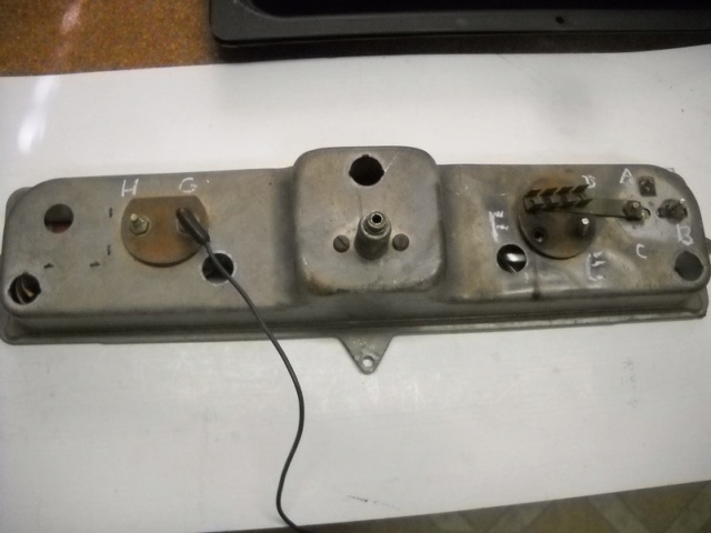
Those represent all the electrical connections on the back of the dash,,,,,,for the gas gauge, ammeter and temp gauge,,,,,,the temp and fuel gauge run on 6 volts,,,,and its interesting,,,,,(and thats being nice) on how Dodge converts 12 volts down to 6 volts just for those 2 gauges by installing the current limiter inside the fuel gauge,,,,Ammeters are bad,,,,,you cant run like 60 amps through a gauge for too long,,,,so they get red hot and burn off the screw terminal,,,,the picture is for future reference when people want to talk dodge dash problems,,,,AND,,,,,for my buddy Jens to show just how his idea of putting an electronic fuel gauge with condensers and a diode compares to buying a $100 fuel gauge on Ebay,,,,,,,I just put out some out some information to get the conversation started,,,,,a starting place for people to jump in with their ideas and solutions,,,,,if you want to know what each of those terminals that I put letters on, I will tell you,,,,,
vanny- Moderator
- Number of posts : 14775
Location : Ashburnham, MA
Age : 65
Registration date : 2012-09-22
Yes, Johnny-5 needs more input! Thanks Don, knowledge is king!
_________________
“The future will soon be a thing of the past."
http://public.fotki.com/Vintage-Vans/vintage-vans-es/ruff-diamond-1/?cmd=fs_slideshow
69- Number of posts : 434
Location : Germany, Nds
Registration date : 2016-10-18
Perfect, Don. E and F are the ammeter posts. You can easily see the problem Don is referring to - the dark color is there for a "reason": HEAT. And you don't want that heat right behind the dash, that's only paper to isolate the posts from the grounded dash metal. The heat usually comes from contact-resistances; corroded posts, cables, nuts loose etc. You can see the white stuff covering the post? That WILL be the cause of contact resistance, which converts amps into heat, heat on paper makes burns - et voila!
Back to the lettering. D which is also connected to C is 12V-IGN. C is the input post for the voltage limiter inside the fuel gauge. I'm 90% sure that B is connected to the fuel sending unit and A is the 6V output connected to the temp gauge H and G is connected to the temp sending unit.
If I am wrong, A and B might be the other way round. For the temp gauge it doesn't matter, as the only relevant point is, that it needs to be connected to the 6V output of the fuel gauge!
If you put a 5V electronic limiter instead of the "fuel gauge limiter", you of course need to disconnect C (just remove the nut and pry the strip away from the dash. Best you isolate it properly. The electronic limiter output would be connected to A (keeping the connecting cable to the temp gauge in place).
69- Number of posts : 434
Location : Germany, Nds
Registration date : 2016-10-18
Here's a good description (ok, wiki-type details).
https://en.wikipedia.org/wiki/78xx
With a good schematic for the limiter. The diode is quite important in a car application, condensers C2 and C3 are tiny 100nF standard types, C1 and C4 might vary in size a bit. Left side is 12V/IGN input, right side is 5v output.

https://en.wikipedia.org/wiki/78xx
With a good schematic for the limiter. The diode is quite important in a car application, condensers C2 and C3 are tiny 100nF standard types, C1 and C4 might vary in size a bit. Left side is 12V/IGN input, right side is 5v output.

donivan65- Governor
- Number of posts : 12220
Location : San Diego, California
Registration date : 2008-05-12
You got it right A sends 6v over to G on the temp gauge by a wire,,,,,this post is going to show up when the Dodgers search for "why is smoke coming out from under my dash",,,,,,,do you have a link to this electronic fuel gauge,,,,,is it a direct replacement?
gary h- Number of posts : 474
Location : tn.
Registration date : 2012-10-19
I had the truck out yesterday to get gas and noticed the Fuel and Temp.gauges fluctuating about 1/4' (back and forth).I have extra gauges so I think I will replace the fuel gauge.The Voltage limiter is located in fuel gauge? Can it be bench tested ? I don't think the tank unit is the problem because the Temp.gauge being unsteady.

dix- Moderator 1st Class

- Number of posts : 8729
Location : pittsburgh pa
Age : 66
Registration date : 2008-05-29
i would dout the tank flote is the culprit
_________________
still vannin since 1974

sweetvan- Number of posts : 242
Location : Ventura, CA, 93003
Registration date : 2013-12-16
Isn't the metal strip between D & C the actual resistance that reduces the voltage? I'd think that it should be raised up off the gauge housing so that it will not ground out. If it did touch, it would short and get hot and maybe blow the fuse for the instruments. It should connect to C and be insulated from the housing. Right?
69- Number of posts : 434
Location : Germany, Nds
Registration date : 2016-10-18
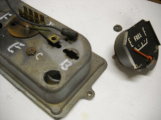
The metal between C and D is plain metal, zero resistance. It is connected to 12v and MUST NOT touch the housing, that'll be a (near) worst case short.
Normally, there's a approx. 1/16" thick paper-type insulation below it and both the two gauges (as can be seen on the left side). You can still see the "shadow" around the fuel gauge studs - and there's a reason for them.
The voltage is reduced by a mechanical limiter inside the fuel gauge. That's why it has three studs A, B and C.


|
|
|