


How to: Use Relays in Your Wiring Projects.
I used components available at “Summit” for this “How to:”
An electrical system is only as reliable as its components. One easy way to increase system reliability and performance is by using relays to switch devices (lights, fuel pumps, fans, etc.) on and off. A relay is an electrode-mechanical switch. An electrode-magnet (also called a coil) is used to pull a set of contacts, or pins, together.
Why not just use an ordinary on/off switch, you ask? Here are some reasons why relays are better than switches:
1. A correctly wired relay will provide the shortest electrical path (i.e. shortest wire length) between the battery and the device(s) controlled by the relay. Combined with the proper gauge wire, this will minimize the voltage drop between the battery and the device, allowing it to function at peak performance levels.
3. Relays allow you to use the proper size fuse for each device, and to place the fuses closer to the battery.
4. If you use a vehicle’s stock wiring and switches to control aftermarket devices like high output lighting, relays will not overload or stress the OEM components. The average automotive relay can also handle a much higher current load than a switch (about 30 amps vs. 3-20 amps).
Relay Types
It’s important to know a relay’s pin configuration and function before connecting devices to it. Many automotive relays are similar in appearance and pin configuration and will plug into the same relay socket, but are completely different in the switching duties they perform.
The most common type of relay used in automotive applications is the single pole/ double throw (SPDT). Also known as the Bosch relay, the SPDT has a common, movable contact that moves between two fixed contacts, termed Normally Open and Normally Closed. When the relay is off, the common and Normally Closed contacts are connected. When the relay is energized the common is switched over the Normally Open contact.
Another type of relay is the single pole/single throw (SPST). The SPST is often found in the wiring harnesses for aftermarket lighting; it has a common contact and two Normally Open contacts that are internally connect. When the switch is activated, the contacts are connected.
When power is removed from a relay’s electrode-magnet, a high voltage spike occurs. This spike can hurt on-board computers or other sensitive electronics. If your system has such devices, it’s a good idea to use replays with an internal shorting diode. The diode forces the voltage spike back into the electrode-magnet, where it dissipates as heat.
Relays can help you make an electrical system perform better and run reliably. That’s why you’ll find them in most quality aftermarket lighting systems and wiring harnesses. Once you use them, you’ll wonder why you ever did without ‘em!

This is the bottom view of a typical single pole/double throw (SPDT) Bosch-type relay, showing the pin configuration. Pin #30 is the common switch; it moves between pins #87 (Normally Open) and #87A (Normally Closed). Pin #86 is for the 12-volt positive lead, and pin #85 is for ground.
This circuit diagram of an inactive SPDT relay with no power applied to pins 85 and 86 (ground and 12 volt positive). Pin #30 (common) and Pin #87A (Normally Closed) are connected.
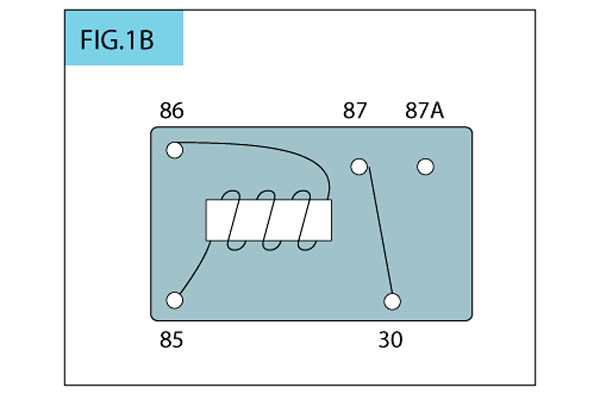
This diagram shows an active SPDT relay with power applied to pins 85 and 86. Pin #30 and pin #87 (Normally Open) are connected.
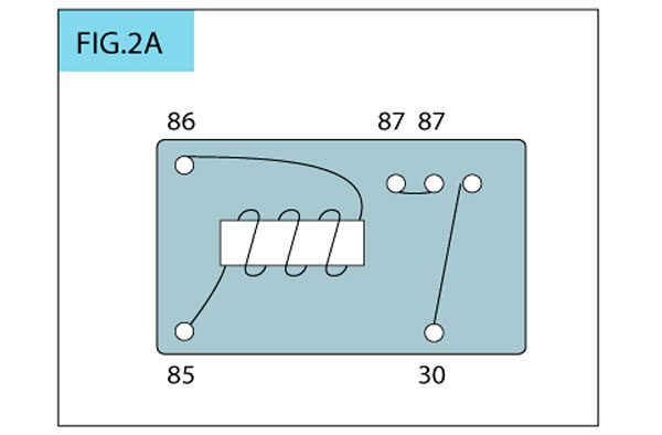
This diagram shows how another type of relay, the single pin/single throw (SPST) operates. It has a #30 pin (common) with two #87 pins (Normally Open) that are connected internally. This type of relay allows you to wire two systems (such as a pair of lights) to activate at the same time.
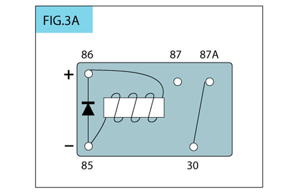
Here is a circuit diagram of a SPDT relay with a shorting diode. The diode prevents the voltage spike of relay deactivation from harming computers and other sensitive electronics.
~~~~~~~~~~~~~~~~~~~~~~~~~~~~~~~~~~~~~~~~~~~~~~~~
Here’s some examples of proper relay use and uses.
Electric Fan:
When wiring an electric fan, make sure the positive ignition lead is one that turns off when the starter is engaged. You can use a thermostat housing that allows the thermo switch to be mounted after the thermostat. If you are installing an engine oil or trans fluid-cooling fan, you can mount the thermo switch in the engine oil or transmission pan.
Fuel Pump:
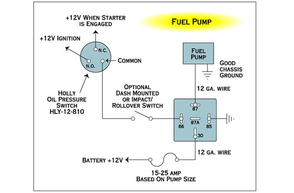
When wiring an electric fuel pump, we strongly recommend using an oil pressure cutoff switch for safety. The switch cuts off power to the pump when oil pressure goes below 5 psi, protecting you from a potential fire. If you are using the pump to feed a nitrous oxide system, you don't need to use the pressure switch's N.C. terminal. Instead, wire a 12-volt positive lead from the nitrous arming switch to the switch's N.O. terminal. The pump is activated only when the nitrous system is armed.
Auxiliary Lights:
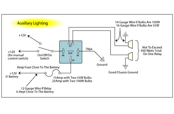
This is a typical auxiliary lighting circuit. The second 12-volt positive lead from the on-off switch can connect to an ignition-activated system to give you manual control. For fog lights: connect the 12-volt positive lead to the positive wire on the parking lights. Connect the ground wire from the relay to the high beam positive wire so the fog lights will turn off when the highs are on. For driving or roof lights: connect the positive lead to the high beam positive wire, and the relay ground to the chassis. For auxiliary low beams: connect the positive lead to the headlight positive wire before it feeds into the high/low beam selector switch. This allows the auxiliary beams to be on when either high or low beams are on. If local laws require the auxiliary lows to turn off when the high beams are on, connect the positive lead to the low beam positive wire. The relay ground in both cases goes to the chassis.
Upgrading Headlights:
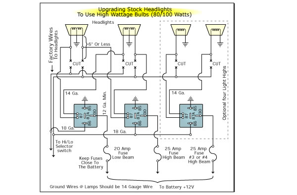
This diagram is for using high-wattage bulbs with stock headlights. Upgrading to 80-100 watt bulbs definitely requires the use of relays. The relay system bypasses the stock headlight wiring, which isn't heavy duty enough to handle the increased wattage of the new bulbs. Make sure the ground wires for the new bulbs is at least 14-gauge. This system retains all stock light controls.
Electric Water Pump:
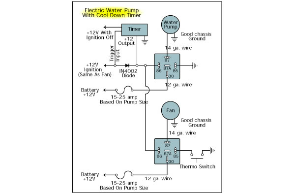
A cool-down timer allows the water pump to continue circulating after the engine has been shut off to dissipate damaging engine heat. A timer setting of 5 minutes should be plenty for most engines. Make sure the band on the diode on the ignition wire (which prevents power from going back through the system when the ignition switch is turned off) is facing the relay. The timer is available pre-made, or can be made from a "555 Chip" available at your local Radio Shack.
DanTheVanMan (2011)
I used components available at “Summit” for this “How to:”
An electrical system is only as reliable as its components. One easy way to increase system reliability and performance is by using relays to switch devices (lights, fuel pumps, fans, etc.) on and off. A relay is an electrode-mechanical switch. An electrode-magnet (also called a coil) is used to pull a set of contacts, or pins, together.
Why not just use an ordinary on/off switch, you ask? Here are some reasons why relays are better than switches:
1. A correctly wired relay will provide the shortest electrical path (i.e. shortest wire length) between the battery and the device(s) controlled by the relay. Combined with the proper gauge wire, this will minimize the voltage drop between the battery and the device, allowing it to function at peak performance levels.
3. Relays allow you to use the proper size fuse for each device, and to place the fuses closer to the battery.
4. If you use a vehicle’s stock wiring and switches to control aftermarket devices like high output lighting, relays will not overload or stress the OEM components. The average automotive relay can also handle a much higher current load than a switch (about 30 amps vs. 3-20 amps).
Relay Types
It’s important to know a relay’s pin configuration and function before connecting devices to it. Many automotive relays are similar in appearance and pin configuration and will plug into the same relay socket, but are completely different in the switching duties they perform.
The most common type of relay used in automotive applications is the single pole/ double throw (SPDT). Also known as the Bosch relay, the SPDT has a common, movable contact that moves between two fixed contacts, termed Normally Open and Normally Closed. When the relay is off, the common and Normally Closed contacts are connected. When the relay is energized the common is switched over the Normally Open contact.
Another type of relay is the single pole/single throw (SPST). The SPST is often found in the wiring harnesses for aftermarket lighting; it has a common contact and two Normally Open contacts that are internally connect. When the switch is activated, the contacts are connected.
When power is removed from a relay’s electrode-magnet, a high voltage spike occurs. This spike can hurt on-board computers or other sensitive electronics. If your system has such devices, it’s a good idea to use replays with an internal shorting diode. The diode forces the voltage spike back into the electrode-magnet, where it dissipates as heat.
Relays can help you make an electrical system perform better and run reliably. That’s why you’ll find them in most quality aftermarket lighting systems and wiring harnesses. Once you use them, you’ll wonder why you ever did without ‘em!
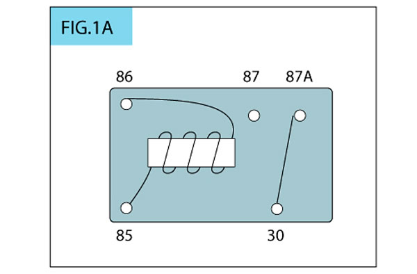
This is the bottom view of a typical single pole/double throw (SPDT) Bosch-type relay, showing the pin configuration. Pin #30 is the common switch; it moves between pins #87 (Normally Open) and #87A (Normally Closed). Pin #86 is for the 12-volt positive lead, and pin #85 is for ground.
This circuit diagram of an inactive SPDT relay with no power applied to pins 85 and 86 (ground and 12 volt positive). Pin #30 (common) and Pin #87A (Normally Closed) are connected.
This diagram shows an active SPDT relay with power applied to pins 85 and 86. Pin #30 and pin #87 (Normally Open) are connected.
This diagram shows how another type of relay, the single pin/single throw (SPST) operates. It has a #30 pin (common) with two #87 pins (Normally Open) that are connected internally. This type of relay allows you to wire two systems (such as a pair of lights) to activate at the same time.
Here is a circuit diagram of a SPDT relay with a shorting diode. The diode prevents the voltage spike of relay deactivation from harming computers and other sensitive electronics.
~~~~~~~~~~~~~~~~~~~~~~~~~~~~~~~~~~~~~~~~~~~~~~~~
Here’s some examples of proper relay use and uses.
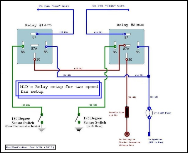
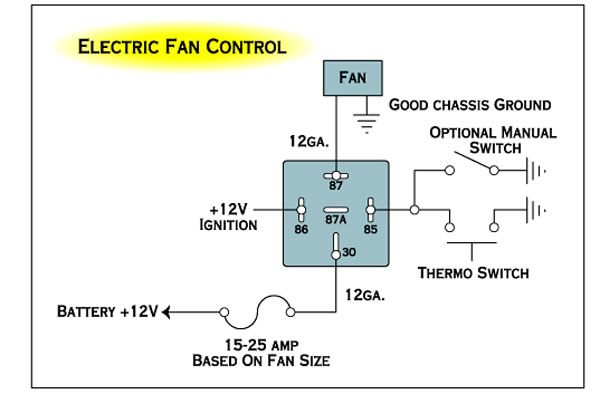
Electric Fan:
When wiring an electric fan, make sure the positive ignition lead is one that turns off when the starter is engaged. You can use a thermostat housing that allows the thermo switch to be mounted after the thermostat. If you are installing an engine oil or trans fluid-cooling fan, you can mount the thermo switch in the engine oil or transmission pan.
Fuel Pump:
When wiring an electric fuel pump, we strongly recommend using an oil pressure cutoff switch for safety. The switch cuts off power to the pump when oil pressure goes below 5 psi, protecting you from a potential fire. If you are using the pump to feed a nitrous oxide system, you don't need to use the pressure switch's N.C. terminal. Instead, wire a 12-volt positive lead from the nitrous arming switch to the switch's N.O. terminal. The pump is activated only when the nitrous system is armed.
Auxiliary Lights:
This is a typical auxiliary lighting circuit. The second 12-volt positive lead from the on-off switch can connect to an ignition-activated system to give you manual control. For fog lights: connect the 12-volt positive lead to the positive wire on the parking lights. Connect the ground wire from the relay to the high beam positive wire so the fog lights will turn off when the highs are on. For driving or roof lights: connect the positive lead to the high beam positive wire, and the relay ground to the chassis. For auxiliary low beams: connect the positive lead to the headlight positive wire before it feeds into the high/low beam selector switch. This allows the auxiliary beams to be on when either high or low beams are on. If local laws require the auxiliary lows to turn off when the high beams are on, connect the positive lead to the low beam positive wire. The relay ground in both cases goes to the chassis.
Upgrading Headlights:
This diagram is for using high-wattage bulbs with stock headlights. Upgrading to 80-100 watt bulbs definitely requires the use of relays. The relay system bypasses the stock headlight wiring, which isn't heavy duty enough to handle the increased wattage of the new bulbs. Make sure the ground wires for the new bulbs is at least 14-gauge. This system retains all stock light controls.
Electric Water Pump:
A cool-down timer allows the water pump to continue circulating after the engine has been shut off to dissipate damaging engine heat. A timer setting of 5 minutes should be plenty for most engines. Make sure the band on the diode on the ignition wire (which prevents power from going back through the system when the ignition switch is turned off) is facing the relay. The timer is available pre-made, or can be made from a "555 Chip" available at your local Radio Shack.
DanTheVanMan (2011)