I did a lot of fabricating over the long weekend! Well, I should say I spent a
lot of time doing a
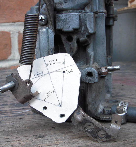
little fabricating! Worked out a good way to hook up the 700R4's TV cable to the carburetor linkage. They all say the geometry of this cable and its relationship to the throttle is very important to get the shifting right. This is the diagram everyone refers to:
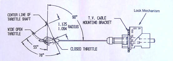
Note: They show the cable mounted below the pivot point, but I put mine above. It works the same either way.
They sell brackets for V8's with popular carbs but none for a sideways-mounted one barrel!! I've seen guys attach the cable to one of the many throttle linkage rods or bell cranks, but I think it should be right on the carb's bell crank. No sense involving all the accumulated slop in all that other linkage.
My carb is a Rochester Monojet from a 2nd Gen, I think, so the carb bell crank lever may not look like yours. But using a procedure similar to this should work for yours.
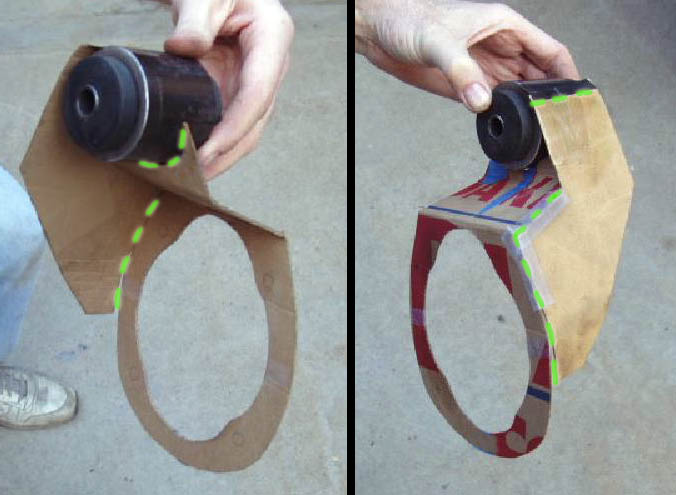
My initial plan was to attach a flat piece of metal to the bell crank and then mount the cable connector pin to this. I trimmed a piece of thin cardstock so it would hold itself onto the bellcrank. I marked the bell crank's pivot point and some holes I could use for mounting the metal plate. Then I used a compass to draw a 1.1" radius arc from the pivot point. This is the path the cable's pin will move in. (To get the right amount of travel on the cable, the cable connector pin needs to be mounted about 1.1" away from the pivot point of the carb bell crank -- in other words, with a radius of 1.094 to 1.125 inches from the throttle plate's shaft.)
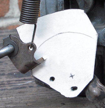
As you can see in the diagram up top, everything is based on a line perpendicular to TV cable. The idle position is 23° this side of that line, and full throttle is 55° the other way. (This Rochester did move a total of 78° like in the diagram.) So next I had to determine at which angle the TV cable would come to the carb. I found there was enough room to run it between the valve cover and the air cleaner. This put the cable coming down at a bit of an angle. Using a straight edge I drew this angle on the template, with it touching the top of the circle. And another line 90° to that, running down to the pivot point:

Then I used a protractor to draw a line 23° to the right of that line. And finally this gave me the mounting point for the connector pin! (Where it says "idle")
Now, here's where I'll save you some wasted time. I cut this same shape out of thin metal and attached it with screws to the bell crank. (Sorry, no picture.) Hooked the TV cable up to it and was feeling pretty good about myself! This had only taken a couple hours. And then I "gave it some gas", rotating the carb's bell crank and found that the cable end ran into the carb's return spring!! D'oh!
I toyed with the idea of moving the spring further out but I didn't want to do that. I tried putting the plate on the other side of the bell crank. This would move the pin in far enough to clear the spring. But the plate had to be so cut up to clear the shaft and stuff that it seemed too flimsy. Then I got an idea. I now knew exactly where this pin needed to be, so maybe I could just run some thicker steel up to that point and weld the pin to it.
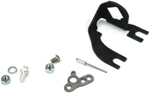
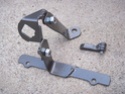
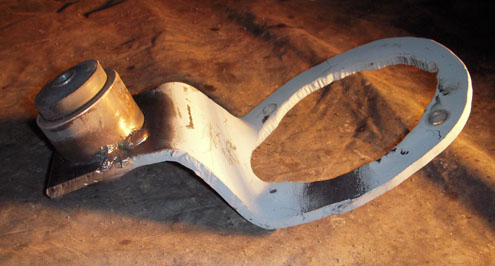
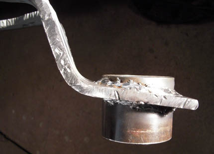
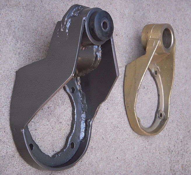
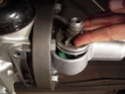
Anyhow, sometime the next day I came up with this simple little gem:
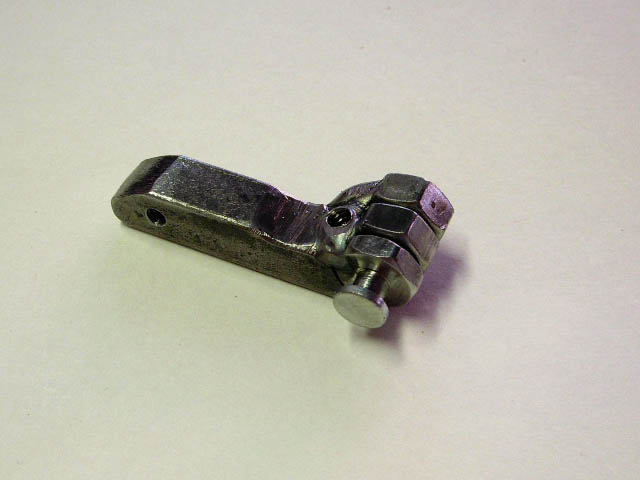
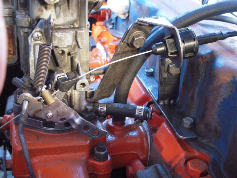
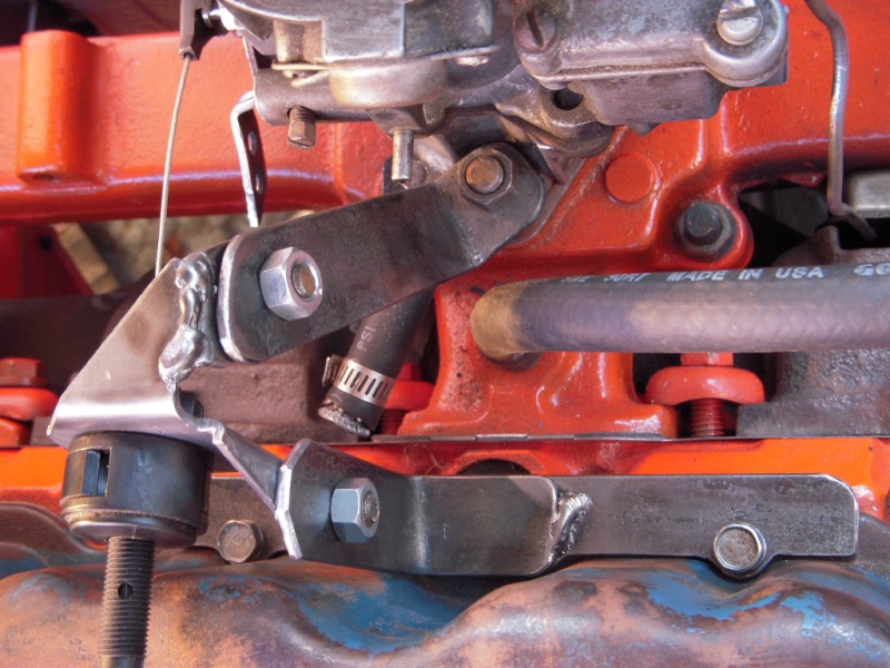
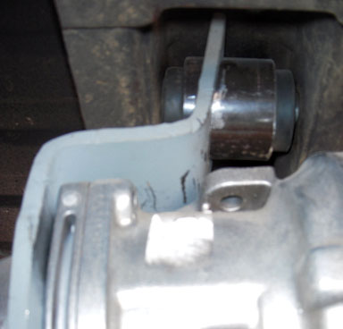
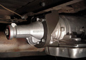
I put two nuts on the pin and welded it to a piece of 3/8" steel bar. Drilled and tapped two holes to mount it to existing holes in the bell crank. Here's how it looks in place:
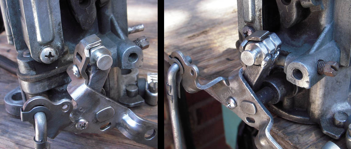
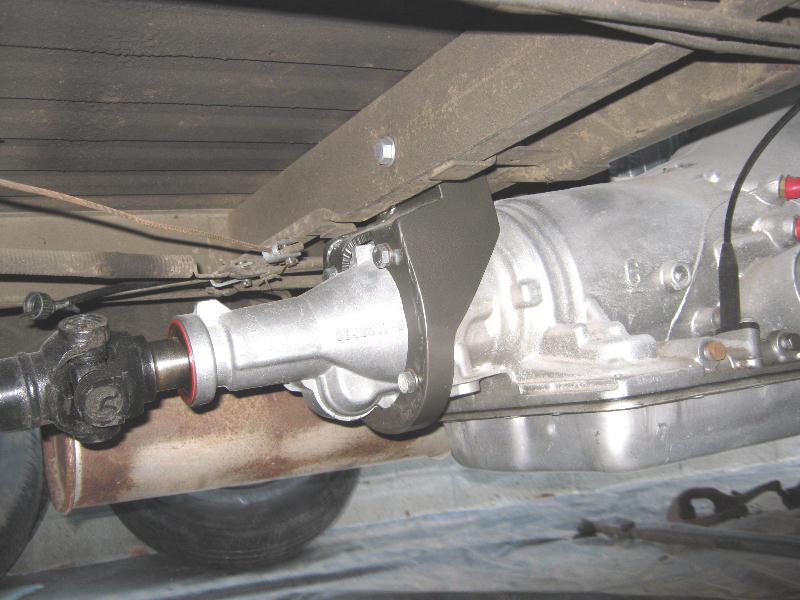
Very nice. All that work done but now I had to mount the actual TV cable housing to the engine at the angle I had drawn on the template... I'll post that story tomorrow.